626
Item nr.
| Production | The Netherlands, 2026. |
|---|---|
| Bands | MW (733-2128kc), SW1 (1.8-4.6Mc), SW2 (4.6-12.2Mc), SW3 (12-27Mc). |
| Semi- conductors | 2SA70 (osc), LED, Cymometer. |
| Cabinet | Plastic. Size 27x17x9cm. Weight 2kg. |
| Power | Batt 6V (4xD), 2mA (40mA with cymometer). |
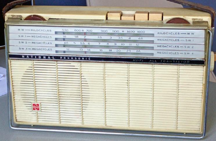 T-430 portable, on which this project was based, seems like a smaller version of the National T-100 I had before. Four band portable, has Tropical Band and Shortwave, and fine tuning. After removal of some obsolete parts and addition of a cymometer, it can be placed next to an ordinary AM radio without any need for connection or modification, and serve two functions. First, it allows to hear Single Side Band transmissions. Second, the frequency of a station can be determined with 10Hz precision.
 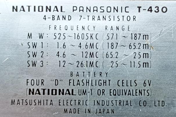 These are the frequencies originally rceived by the T-430. The Kaketoe covers about the same ranges, except that Medium Wave runs from 733 to 2100kHz.
| Obtained | 4/2026 from NVHR meeting (Jan) and home made. |
|---|---|
| Condition | 8. |
| Value (est.) | 4,7€. |
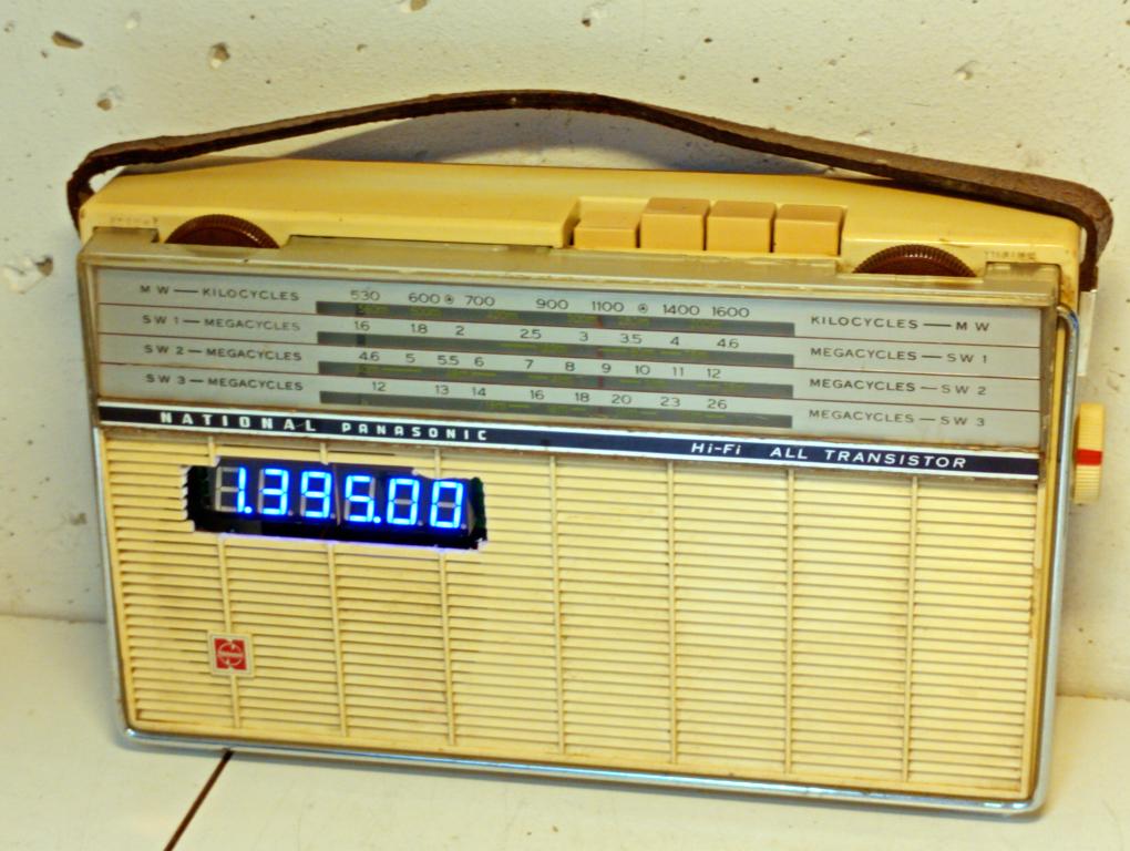
| Sound sample | PLAY SOUND A Radio frequent BFO with frequency counter reveals the new insight that most hams, though it is not obligatory, work at an integer kiloHertz frequency. So the best position of the BFO is mostly xxx.00 or something close. And clearifying by frequency counter turns out to give clearer rusults than by ear. |
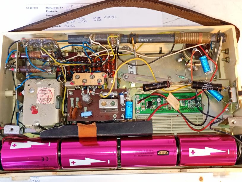
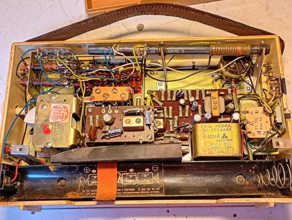 The ferrite rod has coils for MW and TB, the two Short Wave bands use the loop aerial that can be folded out in front. To take out the chassis, the antenna connectors can be plugged apart from the chassis. In the right, next to the tuning capacitor, you can see the little fine tuning knob.
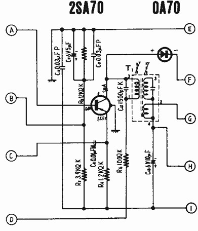 The converter stage is a self-oscillating 2SA70, which suffered from whiskers, but I could bring the oscillator to life by disconnecting the shield and connecting pin I to +6V. The oscillator stage radiates sufficiently to be picked up by a working radio placed next to it, so no connection of the output of the oscillator is needed.
 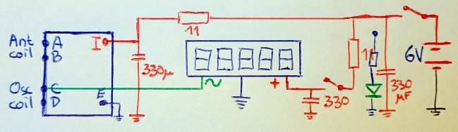 Only I connected pin C (oscillator coil) to the cymometer. I left the antenna coils in place, though I could have replaced them by a connection between A and B. The main PCB and loudspeaker were removed.
 Directly connecting oscillator and cymometer to the 6V battery gave some interference and a dirty signal, so I decoupled the two main circuits by two 11R resistors (black) and three 330μF capacitors (blue). Originally I included a green LED because I often forget to switch off my battery fed equipment. But because the LED took twice as much current as the oscillator, I disconnected this LED and made a white OFF indication on the power switch.
A minor detail is that the oscillator of a radio runs 455kHz higher than the tuned frequency, so the ranges of the oscillator didn't correspond to the normal ranges of the radio and the dial. For the MW band, I bridged the padder capacitor by 47nF, bringing down the lower limit from 950 to 733kHz. For the three shortwave bands, I managed to align the coils to bring the range down to close to the original radio frequent range.