308
Item nr.

| Production | The Netherlands, 2008.
Price was 37 Euros. |
|---|---|
| Bands | Rx: LW, MW, FM; Tx: MW. |
| Semi- conductors | 5 ICs: CD4053B (modulator), CD4060B (crystal oscillator plus binary divisor), CD4046 (Oscillator), CD40103 (programmable divisor), LM358 (audio amp). |
| Cabinet | Trash casseteradio. Size 29x17x9cm. |
| Power | 12V DC (Adapter takes 2.2W; regulated power supply takes 8W). |
In Europe the frequency grid is 9kHz, so the transmitter first generates a stable and precise 9kHz signal; this happens in CD4060B, housing an oscillator controlled by a 9.216kHz crystal and a divisor. Any multiple of this frequency can be generated by IC CD4046B, a voltage controlled oscillator, together with frequency divisor IC CD40103. The division is controlled by dip switches. The audio input is amplified by IC LM358M, and then, by way of modulation, chopped in the switching IC CD4053B. This makes an extremely interesting transmitter design, because so far no coils, and hardly any capacitors are needed. The frequency stablitiy is derived from the crystal. The modulated output is fed through an impedance matcher that has four small coils.

 Only a few years later I built the unit in a larger project. From an Aristona cassette recorder I removed the cassette part and built in the transmitter. This gives a single unit that can retransmit FM broadcasts on the AM band.
| Obtained | 4/2008 from J. van Schaik. |
|---|---|
| Condition | 7. |
| Disposed | Sold 8/2025. |
| Sound sample | PLAY SOUND Most radios play better from the Ottozender than from a real station. You hear a small Muse fragment, played from the Tesla 420U. |
 Then I found out that Mr Van Schaik in Lekkerkerk sells construction kits, containing the pcb plus all the parts that must be connected to it. The kits were on sale at the NVHR Swap Meeting in Driebergen, and on April5, 2008, I bought one. On the evening of that day, my Ottozender looked like the picture on the right. My next hobby evening was used for studying the building instructions and soldering a few cables to connect the audio source, power supply, and antenna.
 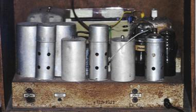 Of course it was but still I managed to screw things up considerably. The four coils looked a bit different from those I'm used to (see picture of CeBe on the left) so I didn't recognise them and thought they were resistors. Soldering a resistor to a pcb is not so hard, and even if you mistake, you can take it away quite easily.
 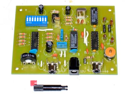 But ICs with 14 connections are harder! You must put them well in place (manage to push 7 leads simultaneously through the board, and then the other 7) and then solder the leads. After that, it is virtually impossible to remove them again, because melting one joint at a time does not allow to physically move the IC. But after perfectly soldering my first IC, I had to find a solution for unsoldering ICs... because I had soldered IC1 in the location of IC4.
But I managed to get it off again, and despite this delay I got all parts on the board in one evening; see picture taken at the end of evening 2. Two rather insignificant parts were missing from the kit. It was supposed to have five 100n capacitors, but it had just two small orange ones and two big blue ones. So this explains why IC5, right to the dip switch, is decoupled with a 250V capacitor from a deceased TV. R20 of 560k was also missing, so right behind IC5 you see two 1M3 resistors in parallel.
 The next day I didn't have much time, but I found myself paralysed and unable to leave the house without a test. I tried an old wall socket power supply, but this gave hum, and a power supply of an old intercom. That one plus a 4700uF capacitor gave hum-free operation and I found out that the Ottozender could be received through the house! That was good, because it proved that IC1 had survived the unsoldering plus two soldering operations.
 A few days later my Ottozender became a Novelty set, because I built it into an old ice cream box. We eat a lot of ice cream and I usually take the empty boxes in my work shop for storing radio parts. The picture shows it with the power supply, capacitor plus 91 Ohm decoupling resistor. The power supply had a small pilot light, connected with the green wires, which I included in the front panel. The power switch for the bug is a chord switch.
 To use the Ottozender, the desired frequency is selected with the dip switches. I found 540kHz to work fine for me. Then an audio source is connected, like the Sony radio that can play FM stations. After a little tweaking, the FM transmitter becomes copyable on all AM radios in the house. A few measurements and tests: