262
Item nr.

| Production | Germany, 1964.
Price was 1000DM. |
|---|---|
| Bands | LW, MW, SW, FM (87.5-104 MHz). |
| Tubes | ECC85 (FM tuner), ECH81 (converter), EAF801 (IF amp), EF184 (IF amp for FM), EM87 (tuning indicator), EM87 (stereo indicator), ECC808 (audio left channel), ECC808 (audio right channel), ECC83 (phase inverters), ELL80 (left output), ELL80 (right output). |
| Semi- conductors | AF126 (19kHz amp), AF126 (38kHz amp), AC126 (left amp), AC126 (right amp), 2x AC126 (reverb amp), BA102 (AFC), 2x OA79 (FM det.), 2x AA119 (19kHz detector), 4x AA119 (stereo demux), AA119 (limiter), B250C185 (rectifier). |
| Cabinet | Wood. Size 65x26x24 cm. |
| Power | AC, 125-220V, 75W. |
| Documents |  . . |
 Also I already had a seven set, the BX750A. This is my first eight, and as can be expected, it comes with a special feature: the Reverbeo unit that makes your room sound like an echo chamber. The photo on the left shows this reverb spring assembly.
 So, a more intricate solution was invented. The L and R signal were converted in the transmitter to a Mono signal M = L+R and a Stereo signal S = L-R. In the receiver, the Left signal is found back by summing: L = M+S and the right channel by distracting R = M-S (I ignore division by 2). For transmission, the Stereo signal is lower-sideband odulated at a 38kHz carrier frequency, and a signalling tone of 19kHz is added to activate the decoder. 
What happens in the decoder? Of course, to achieve Hi-Fi detection of a single-sideband coded stereo signal, a very accurate BFO signal is needed. This is not generated in the radio, but derived by two-phased rectification of the 19kHz pilot signal, which also activated the stero pilot lamp on the radio. Then, the stereo signal S is recovered by multiplying the detected signal by the 38kHz tone, after which it is added and subtracted from the same signal. In the schema you can see that the incoming signal is detected, then a 19kHz tone is filtered out and rectified with GR1 and GR2, then the SSB detection takes place in GR3-6.
 A single ELL80 (or ECLL800) tube produced about 20 to 25 Watts of power, so a stereo radio with two of these plays continuously with the heat production of a quite big soldering iron in the center. It requires a bit of care in the air circulation design to get rid of this. Of course, when you repair the radio, it can be handy to put it on one of the sides, but this may situate your soldering iron right under the stereo demultiplexer, which would become overheated. Hence the warning (in German) on the decoder, to never put the radio in that position.
| Obtained | 9/2005 from Ben Voorsluijs, SN=WA12977. |
|---|---|
| Condition | 7. |
| Disposed | Sold 12/2013. |
| Sound sample | PLAY SOUND Petula Clark sings softly to forget her pains. Can you hear when the Reverbeo is switched off? |
The only real problem with the radio was a defective FM. 
 I replaced a capacitor and resistor in the screen grid circuit of the EF184 (which amplifies for FM only), but this did not remedy the problem, so I decided I had to open the FM tuner. Because I didn't want to have to restring the tuning dial chord, I managed to fix the tuning wheel of the tuner with a rubber band before taking it off the tuner. In this way, the dial chord was fixed all through the repair, and indeed, afterwards I could put the wheel back and I didn't have to restring. Inside the tuner, a resistor had overheated and increased value, causing the ECC85 to run on low voltage so it didn't oscillate. This was very easy to repair.
 After the remounting of the tuner, I had shorted the heater supply line to ground, causing the 6A heater fuse to blow (photo), but I managed to repair it by soldering the ends together.
 Originally the radio came with matching loudspeakers, not only in impedance and wood color, but also in size; each loudspeaker was exactly as big as the radio turned on its side (photo). I got it without speakers, but found some two way speakers in the local thrift shop. I completed the setup with a Philips N2511 stereo cassette deck.
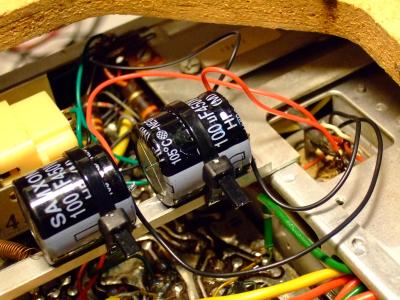
 A little hum remained, as was noticable in our Sixties Party in 2010. So I installed a few extra filter caps under the chassis (left), after which the radio could be used in my new office in BBL.
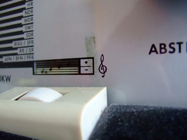
 The radio has some external damages, like the upper corners, and there is a small spot on the dial, as seen on these photos.